
Technical Introduction to OpenEXR
Features of OpenEXR
A unique combination of features makes OpenEXR a good fit for high-quality image processing and storage applications:
- high dynamic range
Pixel data are stored as 16-bit or 32-bit floating-point numbers. With 16 bits, the representable dynamic range is significantly higher than the range of most image capture devices: 109 or 30 f-stops without loss of precision, and an additional 10 f-stops at the low end with some loss of precision. Most 8-bit file formats have around 7 to 10 stops.
- good color resolution
With 16-bit floating-point numbers, color resolution is 1024 steps per f-stop, as opposed to somewhere around 20 to 70 steps per f-stop for most 8-bit file formats. Even after significant processing (for example, extensive color correction) images tend to show no noticeable color banding.
- compatible with graphics hardware
The 16-bit floating-point data format is fully compatible with the 16-bit frame-buffer data format used in some new graphics hardware. Images can be transferred back and forth between an OpenEXR file and a 16-bit floating-point frame buffer without losing data.
Most of the data compression methods currently implemented in OpenEXR are lossless; repeatedly compressing and uncompressing an image does not change the image data. With the lossless compression methods, photographic images with significant amounts of film grain tend to shrink to somewhere between 35 and 55 percent of their uncompressed size. OpenEXR also supports lossy compression, which tends to shrink image files more than lossless compression, but doesn’t preserve the image data exactly. New lossless and lossy compression schemes can be added in the future.
- arbitrary image channels
OpenEXR images can contain an arbitrary number and combination of image channels, for example red, green, blue, and alpha; luminance and sub-sampled chroma channels; depth, surface normal directions, or motion vectors.
- scan line and tiled images, multi-resolution images
Pixels in an OpenEXR file can be stored either as scan lines or as tiles. Tiled image files allow random-access to rectangular sub-regions of an image. Multiple versions of a tiled image, each with a different resolution, can be stored in a single multi-resolution OpenEXR file.
Multi-resolution images, often called “mipmaps” or “ripmaps”, are commonly used as texture maps in 3D rendering programs to accelerate filtering during texture lookup, or for operations like stereo image matching. Tiled multiresultion images are also useful for implementing fast zooming and panning in programs that interactively display very large images.
- ability to store additional data
Often it is necessary to annotate images with additional data; for example, color timing information, process tracking data, or camera position and view direction. OpenEXR allows storing of an arbitrary number of extra attributes, of arbitrary type, in an image file. Software that reads OpenEXR files ignores attributes it does not understand.
- easy-to-use C++ and C programming interfaces
In order to make writing and reading OpenEXR files easy, the file format was designed together with a C++ programming interface. Two levels of access to image files are provided: a fully general interface for writing and reading files with arbitrary sets of image channels, and a specialized interface for the most common case (red, green, blue, and alpha channels, or some subset of those). Additionally, a C-callable version of the programming interface supports reading and writing OpenEXR files from programs written in C.
Many application programs expect image files to be scan line based. With the OpenEXR programming interface, applications that cannot handle tiled images can treat all OpenEXR files as if they were scan line based; the interface automatically converts tiles to scan lines.
The C++ and C interfaces are implemented in the open-source OpenEXR library.
- fast multi-threaded file reading and writing
The OpenEXR library supports multi-threaded reading or writing of an OpenEXR image file: while one thread performs low-level file input or output, multiple other threads simultaneously encode or decode individual pieces of the file.
- portability
The OpenEXR file format is hardware and operating system independent. While implementing the C and C++ programming interfaces, an effort was made to use only language features and library functions that comply with the C and C++ ISO standards.
- multi-view
A “multi-view” image shows the same scene from multiple different points of view. A common application is 3D stereo imagery, where a left-eye and a right-eye view of a scene are stored in a single file.
- deep data
Support for a new data type has been added: deep data. Deep images store an arbitrarily long list of data at each pixel location. This is different from multichannel or ‘deep channel images’ which can store a potentially large, but fixed, amount of information at each pixel. In a deep image, each pixel stores a different amount of data.
This allows for more accurate compositing of objects which occlude each other, and provides a method for storing opacity data in the z direction (particularly useful for stereo images which have atmospheric effects such fog).
- multi-part
Multi-part files allow for storing multiple images in one OpenEXR file. One important application is to store layers of channels separately. This allows for faster access when only a subset of the channels needs reading. It also permits layers to have differing data layout (for example, for different compression, or different layout) and different data windows.
It also allows some layers to be stored as deep data and others as regular images. With multi-part files, different views are stored in different parts.
Overview of the OpenEXR File Format
Definitions and Terminology
Pixel space
Pixel space is a 2D coordinate system with x increasing from left to right and y increasing from top to bottom. Pixels are data samples, taken at integer coordinate locations in pixel space.
Display window
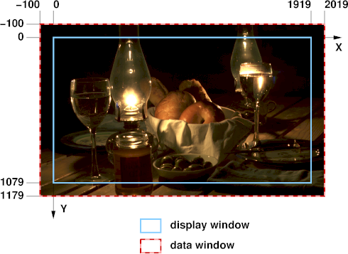
The boundaries of an OpenEXR image are given as an axis-parallel rectangular region in pixel space, the display window. The display window is defined by the positions of the pixels in the upper left and lower right corners, (x min, y min) and (x max, y max).
Data window
An OpenEXR file may not have pixel data for all the pixels in the display window, or the file may have pixel data beyond the boundaries of the display window. The region for which pixel data are available is defined by a second axis-parallel rectangle in pixel space, the data window.
Examples:
Assume that we are producing a movie with a resolution of 1920 by 1080 pixels. The display window for all frames of the movie is (0, 0) - (1919, 1079). For most images, in particular finished frames that will be recorded on film, the data window is the same as the display window, but for some images that are used in producing the finished frames, the data window differs from the display window.
For a background plate that will be heavily post-processed, extra pixels, beyond the edge of the film frame, are recorded and the data window is set to (-100, -100) - (2019, 1179). The extra pixels are not normally displayed. Their existence allows operations such as large-kernel blurs or simulated camera shake to avoid edge artifacts.
While tweaking a computer-generated element, an artist repeatedly renders the same frame. To save time, the artist renders only a small region of interest close to the center of the image. The data window of the image is set to (1000, 400) - (1400, 800). When the image is displayed, the display program fills the area outside of the data window with some default color.
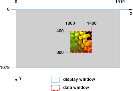
Image channels and sampling rates
Every OpenEXR image contains one or more image channels. Each channel has a name, a data type, and x and y sampling rates.
The channel’s name is a text string, for example R, Z or
yVelocity. The name tells programs that read the image file how to
interpret the data in the channel.
For a few channel names, interpretation of the data is predefined:
name |
interpretation |
|---|---|
R |
red intensity |
G |
green intensity |
B |
blue intensity |
A |
alpha/opacity: 0.0 means the pixel is transparent; 1.0 means
the pixel is opaque. By convention, all color channels are
premultiplied by alpha, so that |
Three channel data types are currently supported:
type name |
description |
|---|---|
|
16-bit floating-point numbers; for regular image data. (See The half Data Type. |
|
32-bit IEEE-754 floating-point numbers; used where the range or precision of 16-bit number is not sufficient (for example, depth channels). |
|
32-bit unsigned integers; for discrete per-pixel data such as object identifiers. |
The channel’s x and y sampling rates, s x and s y, determine for which of the pixels in the image’s data window data are stored in the file. Data for a pixel at pixel space coordinates (x, y) are stored only if
and
For RGBA (red, green, blue, alpha) images, sx and sy are 1 for all channels, and each channel contains data for every pixel. For other types of images, some channels may be sub-sampled. For example, in images with one luminance channel, Y, and two croma channels, RY and BY, sx and sy would be 1 for the Y channel, but for the RY and BY channels, sx and sy might be set to 2, indicating that chroma data are only given for one out of every four pixels. (See also Luminance/Chroma Images).
Projection, camera coordinate system and screen window
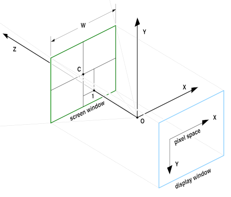
Many images are generated by a perspective projection. We assume
that a camera is located at the origin, O, of a 3D camera coordinate
system. The camera looks along the positive z axis. The positive x
and y axes correspond to the camera’s left and up directions. The
3D scene is projected onto the z = 1 plane. The image recorded by the
camera is bounded by a rectangle, the screen window. In pixel space,
the screen window corresponds to the file’s display window. In the
file, the size and position of the screen window are specified by the
x and y coordinates of the window’s center, C, and by the window’s
width, W. The screen window’s height can be derived from C, W, the
display window and the pixel aspect ratio.
Scan lines
In scan line based files, the image’s pixels are stored in horizontal rows, or scan lines. A file whose data window is (xmin, ymin) - (xmax, ymax) contains ymax - ymin + 1 scan lines. Each scan line contains xmax - xmin + 1 pixels.
Scan line based files cannot contain multi-resolution images.
Tiles
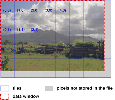
In tiled files, the image is subdivided into an array of smaller rectangles, called tiles. Each tile contains px by py pixels. An image whose data window is (xmin, ymin) - (xmax, ymax) contains ceil(w/px) by ceil(h/py) tiles, where w and h are the width and height of the data window:
The upper left corner of the upper left tile is aligned with the upper left corner of the data window, at (xmin, ymin). The rightmost column and the bottom row of tiles may extend outside the data window. If a tile contains pixels that are outside the data window, then those extra pixels are discarded when the tile is stored in the file.
Levels and level modes
A single tiled OpenEXR files may contain multiple versions of the same image, each with a different resolution. Each version is called a level. The number of levels in a file and their resolutions depend on the file’s level mode. Currently, OpenEXR supports three level modes:
mode name |
description |
|||||||||
|
The file contains only a single full-resolution level. A tiled
|
|||||||||
|
The file contains multiple versions of the image. Each successive level is half the resolution of the previous level in both dimensions. The lowest-resolution level contains only a single pixel. For example, if the first level, with full resolution, contains 16×8 pixels, then the file contains four more levels with 8×4, 4×2, 2×1, and 1×1 pixels respectively. |
|||||||||
|
Like
|
Level numbers, level size and rounding mode
Levels are identified by level numbers. A level number is a pair of
integers, (lx, ly). Level (0,0) is the
highest-resolution level, with w by h pixels. Level (lx, ly) contains
by
pixels, where rf(x) is a rounding function, either floor(x) or
ceil(x), depending on the file’s level size rounding mode
(ROUND_DOWN or ROUND_UP).
MIPMAP_LEVELS files contain only levels where lx = ly. ONE_LEVEL files contain only level (0,0).
Examples:
1. The levels in a RIPMAP_LEVELS file whose highest-resolution
level contains 4 by 4 pixels have the following level numbers:
4 |
2 |
1 |
||
4 |
(0,0) |
(1,0) |
(2,0) |
|
height |
2 |
(0,1) |
(1,1) |
(2,1) |
1 |
(0,2) |
(1,2) |
(2,2) |
|
In an equivalent MIPMAP_LEVELS file, only levels (0,0), (1,1), and (2,2)
are present.
2. In a MIPMAP_LEVELS file with a highest-resolution level of 15 by 17 pixels, the resolutions of the remaining levels depend on the level size rounding mode:
rounding mode |
level resolution |
|---|---|
|
15×17, 7×8, 3×4, 1×2, 1×1 |
|
15×17, 8×9, 4×5, 2×3, 1×2, 1×1 |
Tile coordinates
In a file with multiple levels, tiles have the same size, regardless of their level. Lower-resolution levels contain fewer, rather than smaller, tiles. Within a level, a tile is identified by a pair of integer tile coordinates, which specify the tile’s column and row. The upper left tile has coordinates (0,0). In order to identify a tile uniquely in a multi-resolution file, both the tile coordinates and the level number are needed.
View
A view is a set of image channels, identified by naming convention and the view header attribute. This is usually used to store stereo files, with one view for each eye. Views can be stored in separate files, or together in a single file.
Part
A part is made up of a header and an associated offset table and pixels. In a single-part file, there is one header, one offset table, and corresponding pixel data. In a multi-part file, there can be two or more parts - with each part having one header, one offset table and corresponding pixel data.
Note: This is different from a multi-view file, though you can store views as separate parts if you wish.
Deep Data
OpenEXR 2.0 supports deep data. Deep data images store an arbitrarily long list of data at each pixel location. This is different from multichannel or ‘deep channel images’ which can store a potentially large, but fixed, amount of information at each pixel. In a deep image, each pixel stores a different amount of data.
Deep data can be deep scaline data or deep tile data, the type is defined in the header attributes for that part. Deep data is supported in single-part and multi-part files. In single-part files, it forms the deep scan line block or deep tile component. In multi-part files it can be stored in any chunk regardless of the data type stored in other chunks.
Each pixel contains a list of samples. Each sample contains a fixed number of channels. Typically, the data is used to store deep z-buffer information, where each sample represents the colour at a different depth.
Some users choose to use a different file extension to indicate that an OpenEXR contains deep data (for example, to allow an appropriate viewer to load when double-clicking a file). In such circumstances, the extension DXR (“DepthEXR”) is recommended. However, since v2.0 files can contain a mixture of flat and deep data this practice should be discouraged in favour of the EXR extension.
File Structure
An OpenEXR file is made up of: the header and the pixels.
Header
The header is a list of attributes that describe the pixels. An attribute is a named data item of an arbitrary type. To ensure that OpenEXR files written by one program can be read by other programs, certain required attributes must be present in all OpenEXR file headers:
attribute name |
description |
|---|---|
|
The image’s display and data window. |
|
Width divided by height of a pixel when the image is displayed with the correct aspect ratio. A pixel’s width (height) is the distance between the centers of two horizontally (vertically) adjacent pixels on the display. |
|
Description of the image channels stored in the file. |
|
Specifies the compression method applied to the pixel data of all channels in the file. |
|
Specifies in what order the scan lines in the file are stored in the file (increasing Y, decreasing Y, or, for tiled images, also random Y). |
|
Describe the perspective projection that produced the image. Programs that deal with images as purely two-dimensional objects may not be able so generate a description of a perspective projection. Those programs should set screenWindowWidth to 1, and screenWindowCenter to (0, 0). |
|
This attribute is required only for tiled files. It specifies the size of the tiles, and the file’s level mode. |
In addition to the required attributes, a program may place any number of additional attributes in the file’s header. Often it is necessary to annotate images with additional data, for example color timing information, process tracking data, or camera position and view direction. Those data can be packaged as extra attributes in the image file’s header.
Multi-View Header Attributes
This attribute is required in the header for multi-view OpenEXR files.
attribute name |
notes |
|---|---|
|
Specifies the view this part is associated with (mostly used
for files which stereo views).
* A value of |
For more information about multi-view files, see Storing Multi-View Images in OpenEXR Files.
Multi-part and Deep Data Attributes
These attributes are required in the header for all multi-part and/or deep data OpenEXR files.
attribute name |
notes |
|---|---|
|
The name attribute defines the name of each part. The name of each part must be unique. Names may contain ‘.’ characters to present a tree-like structure of the parts in a file. |
|
Data types are defined by the type attribute. There are four types:
|
|
version 1 data for all part types is described in OpenEXR File Layout. |
|
|
|
Required for parts of type |
Deep Data Header Attributes
These attributes are required in the header for all files which contain deep data (deepscanline or deeptile):
name |
notes |
|---|---|
|
Stores the maximum number of samples used by any single pixel within the image. If this number is small, it may be appropriate to read the deep image into a fix-sized buffer for processing. However, this number may be very large. |
|
There are two deep data types:
|
|
Should be set to 1. ( It will be changed if the format is updated.) |
|
Required if |
Pixels
A chunk is a set of pixel data of a particular format or data type (scanlines (or groups of scanlines), tiles and deep data). The structure of a chunk is defined by the type of pixel data stored in it.
In multi-part files, each part has it’s own chunk and each chunk has a part number at the beginning to correlate them with a header.
Scan line based
When a scan line based image file is written, the scan lines must be
written either in increasing Y order (top scan line first) or in
decreasing Y order (bottom scan line first). When a scan line
based file is read, random access to the scan lines is possible; the
scan lines can be read in any order. Reading the scan lines in the
same order as they were written causes the file to be read
sequentially, without “seek” operations, and as fast as possible.
Tiled image
When a tiled image file is written or read, the tiles can be accessed in any order. When a tiled file is written, the OpenEXR library may buffer and sort the tiles, depending on the file’s line order. If the tiles in a file have been sorted into a predictable sequence, application programs reading the file can avoid slow “seek” operations by reading the tiles sequentially, in the order as they appear in the file.
For tiled files, line order is interpreted as follows:
line order |
description |
||||||||||||||||||||||||||||||||
|---|---|---|---|---|---|---|---|---|---|---|---|---|---|---|---|---|---|---|---|---|---|---|---|---|---|---|---|---|---|---|---|---|---|
|
The tiles for each level are stored in a contiguous block. The levels are ordered like this:
where:
if the file’s level mode is
if the level mode is
if the level mode is In each level, the tiles are stored in the following order:
where tx and ty are the number of tiles in the x and y direction respectively, for that particular level. |
||||||||||||||||||||||||||||||||
|
Levels are ordered as for
|
||||||||||||||||||||||||||||||||
|
When a file is written, tiles are not sorted; they are stored in the file in the order they are produced by the application program. If an application program produces tiles in an essentially random order, selecting
|
Deep Data
Deep data is supported in single-part and multi-part files. In single-part files, it forms the deep scan line block or deep tile component. In multi-part files it can be stored in any chunk regardless of what other data is stored in other chunks.
Data Compression
OpenEXR currently offers several different data compression methods, with various speed versus compression ratio tradeoffs. Optionally, the pixels can be stored in uncompressed form. With fast filesystems, uncompressed files can be written and read significantly faster than compressed files.
Compressing an image with a lossless method preserves the image exactly; the pixel data are not altered. Compressing an image with a lossy method preserves the image only approximately; the compressed image looks like the original, but the data in the pixels may have changed slightly.
Supported compression schemes:
name |
description |
|---|---|
PIZ (lossless) |
A wavelet transform is applied to the pixel data, and the result is Huffman-encoded. This scheme tends to provide the best compression ratio for the types of images that are typically processed at Industrial Light & Magic. Files are compressed and decompressed at roughly the same speed. For photographic images with film grain, the files are reduced to between 35 and 55 percent of their uncompressed size. PIZ compression works well for scan line based files, and also for tiled files with large tiles, but small tiles do not shrink much. (PIZ-compressed data start with a relatively long header; if the input to the compressor is short, adding the header tends to offset any size reduction of the input.) |
ZIPS (lossless) |
Uses the open source deflate library for IETF RFC 1950 compression. Unlike ZIP compression, this operates one scan line at a time. |
ZIP (lossless) |
Differences between horizontally adjacent pixels are compressed using the open source deflate library for IETF RFC 1950 compression. ZIP decompression is faster than PIZ decompression, but ZIP may be larger. Photographic images tend to shrink to between 45 and 55 percent of their uncompressed size. Multi-resolution files are often used as texture maps for 3D renderers. For this application, fast read accesses are usually more important than fast writes, or maximum compression. For texture maps, ZIP is probably the best compression method. Unlike ZIPS compression, this operates in in blocks of 16 scan lines. |
RLE (lossless) |
Differences between horizontally adjacent pixels are run-length encoded. This method is fast, and works well for images with large flat areas, but for photographic images, the compressed file size is usually between 60 and 75 percent of the uncompressed size. |
PXR24 (lossy) |
After reducing 32-bit floating-point data to 24 bits by rounding, differences between horizontally adjacent pixels are compressed with zlib, similar to ZIP. PXR24 compression preserves image channels of type HALF and UINT exactly, but the relative error of FLOAT data increases to about 3×10⁻⁵. This compression method works well for depth buffers and similar images, where the possible range of values is very large, but where full 32-bit floating-point accuracy is not necessary. Rounding improves compression significantly by eliminating the pixels’ 8 least significant bits, which tend to be very noisy, and difficult to compress. Note: This lossy compression scheme is not supported in deep files. |
B44 (lossy) |
Channels of type HALF are split into blocks of four by four pixels or 32 bytes. Each block is then packed into 14 bytes, reducing the data to 44 percent of their uncompressed size. When B44 compression is applied to RGB images in combination with luminance/chroma encoding (see below), the size of the compressed pixels is about 22 percent of the size of the original RGB data. Channels of type UINT or FLOAT are not compressed. Decoding is fast enough to allow real-time playback of B44-compressed OpenEXR image sequences on commodity hardware. The size of a B44-compressed file depends on the number of pixels in the image, but not on the data in the pixels. All files with the same resolution and the same set of channels have the same size. This can be advantageous for systems that support real-time playback of image sequences; the predictable file size makes it easier to allocate space on storage media efficiently. Note: This lossy compression scheme is not supported in deep files. |
B44A (lossy) |
Like B44, except for blocks of four by four pixels where all pixels have the same value, which are packed into 3 instead of 14 bytes. For images with large uniform areas, B44A produces smaller files than B44 compression. Note: This lossy compression scheme is not supported in deep files. |
DWAA (lossy) |
Lossy compression of RGB data by quantizing discrete cosine transform (DCT) components, in blocks of 32 scanlines. More efficient for partial buffer access. |
DWAB (lossy) |
Lossy compression of RGB data by quantizing discrete cosine transform (DCT) components, in blocks of 256 scanlines. More efficient space wise and faster to decode full frames than DWAA access. |
Luminance/Chroma Images
Encoding images with one luminance and two chroma channels, rather than as RGB data, allows a simple but effective form of lossy data compression that is independent of the compression methods listed above. The chroma channels can be stored at lower resolution than the luminance channel. This leads to significantly smaller files, with only a small reduction in image quality. The specialized RGBA interface in the OpenEXR library directly supports reading and writing luminance/chroma images. When an application program writes an image file, it can choose either RGB or luminance/chroma format. When an image file with luminance/chroma data is read, the library automatically converts the pixels back to RGB.
Given linear RGB data, luminance, Y, is computed as a weighted sum of R, G, and B:
The values of the weighting factors, wR, wG, and wB, are derived from the chromaticities of the image’s primaries and white point. (See RGB Color)
Chroma information is stored in two channels, RY and BY, which are computed like this:
The RY and BY channels can be low-pass filtered and subsampled without degrading the original image very much. The RGBA interface in OpenEXR uses vertical and horizontal sampling rates of 2. Even though the resulting luminance/chroma images contain only half as much data, they usually do not look noticeably different from the original RGB images.
Converting RGB data to luminance/chroma format also allows space-efficient storage of gray-scale images. Only the Y channel needs to be stored in the file. The RY and BY channels can be discarded. If the original is already a gray-scale image, that is, every pixel’s red, green, and blue are equal, then storing only Y preserves the image exactly; the Y channel is not subsampled, and the RY and BY channels contain only zeroes.
The half Data Type
Image channels of type HALF are stored as 16-bit floating-point
numbers. The 16-bit floating-point data type is implemented as a C++
class, half, which was designed to behave as much as possible like
the standard floating-point data types built into the C++ language. In
arithmetic expressions, numbers of type half can be mixed freely with
float and double numbers; in most cases, conversions to and
from half happen automatically.
half numbers have 1 sign bit, 5 exponent bits, and 10 mantissa
bits. The interpretation of the sign, exponent and mantissa is
analogous to IEEE-754 floating-point numbers. half supports
normalized and denormalized numbers, infinities and NANs (Not A
Number). The range of representable numbers is roughly 6.0×10⁻⁸ `- 6.5×10:sup:`4; numbers smaller than 6.1×10⁻⁵
are denormalized. Conversions from float to half round the
mantissa to 10 bits; the 13 least significant bits are
lost. Conversions from half to float are lossless; all
half numbers are exactly representable as float values.
The data type implemented by class half is identical to Nvidia’s
16-bit floating-point format (fp16 / half). 16-bit data,
including infinities and NANs, can be transferred between OpenEXR
files and Nvidia 16-bit floating-point frame buffers without losing
any bits.
What’s in the Numbers?
We store linear values in the RGB 16-bit floating-point numbers. By this we mean that each value is linear relative to the amount of light in the depicted scene. This implies that display of images requires some processing to account for the non-linear response of a typical display. In its simplest form, this is a power function to perform gamma correction. There are many recent papers on the subject of tone mapping to represent the high dynamic range of light values on a display. By storing linear data in the file (double the number, double the light in the scene), we have the best starting point for these downstream algorithms. Also, most commercial renderers produce linear values (before gamma is applied to output to lower precision formats).
With this linear relationship established, the question remains, What number is white? The convention we employ is to determine a middle gray object, and assign it the photographic 18% gray value, or .18 in the floating point scheme. Other pixel values can be easily determined from there (a stop brighter is .36, another stop is .72). The value 1.0 has no special significance (it is not a clamping limit, as in other formats); it roughly represents light coming from a 100% reflector (slightly brighter than paper white). But there are many brighter pixel values available to represent objects such as fire and highlights.
The range of normalized 16-bit floats can represent thirty stops of information with 1024 steps per stop. We have eighteen and a half stops over middle gray, and eleven and a half below. The denormalized numbers provide an additional ten stops with decreasing precision per stop.
Recommendations
RGB Color
Simply calling the R channel red is not sufficient information to
determine accurately the color that should be displayed for a given
pixel value. The OpenEXR library defines a chromaticities attribute,
which specifies the CIE x,y coordinates for red, green, blue, and
white; that is, for the RGB triples (1, 0, 0), (0, 1, 0), (0, 0, 1),
and (1, 1, 1). The x,y coordinates of all possible RGB triples can be
derived from the chromaticities attribute. If the primaries and white
point for a given display are known, a file-to-display color transform
can correctly be done. The OpenEXR library does not perform this
transformation; it is left to the display software. The chromaticities
attribute is optional, and many programs that write OpenEXR omit
it. If a file doesn’t have a chromaticities attribute, display
software should assume that the file’s primaries and the white point
match Rec. ITU-R BT.709-3:
CIE x,y |
|
|---|---|
red |
0.6400, 0.3300 |
green |
0.3000, 0.6000 |
blue |
0.1500, 0.0600 |
white |
0.3127, 0.3290 |
CIE XYZ Color
In an OpenEXR file whose pixels represent CIE XYZ tristimulus values, the pixels’ X, Y and Z components should be stored in the file’s R, G and B channels. The file header should contain a chromaticities attribute with the following values:
CIE x,y |
|
|---|---|
red |
1, 0 |
green |
0, 1 |
blue |
0, 0 |
white |
1/3, 1/3 |
Channel Names
An OpenEXR image can have any number of channels with arbitrary names.
The specialized RGBA image interface assumes that channels with the
names R, G, B and A mean red, green, blue and alpha. No
predefined meaning has been assigned to any other channels. However,
for a few channel names we recommend the interpretations given in the
table below. We expect this table to grow over time as users employ
OpenEXR for data such as shadow maps, motion-vector fields or images
with more than three color channels.
name |
interpretation |
|---|---|
Y |
luminance, used either alone, for gray-scale images, or in combination with RY and BY for color images. |
RY, BY |
chroma for luminance/chroma images, see above. |
AR, AG, AB |
red, green and blue alpha/opacity, for colored mattes (required to composite images of objects like colored glass correctly). |
In an image file with many channels it is sometimes useful to group
the channels into layers, that is, into sets of channels that
logically belong together. Grouping is done using a naming convention:
channel C in layer L is called L.C.
For example, an image may contain separate R, G and B channels for
light that originated at each of several different virtual light
sources. The channels in such an image might be called light1.R,
light1.G, light1.B, light2.R, light2.G, light2.B,
etc.
Layers can be nested. A name of the form L1.L2.L3 … Ln.C means that
layer L1 contains a nested layer L2, which
in turn contains another nested layer L3, and so on to
layer Ln, which contains channel C.
For example, light1.specular.R identifies the R channel in the
specular sub-layer of layer light1.
Note that this naming convention does not describe a back-to-front stacking order or any compositing operations for combining the layers into a final image.
For another example of a channel naming convention, see Storing Multi-View Images in OpenEXR Files.
Deep Data - Special Purpose Channels and Reserved Channel Names
Deep data parts reserve a set of channel names for sorts of data often used by developers. Only use these channel names for the correct purpose (listed below). If there is a reserved channel name for the data you are handling, always use the appropriate channel name.
name |
definition |
notes |
|---|---|---|
|
depth of front (closest point) of sample [1] |
All samples should be sorted according to their |
|
Depth of back (farthest point) of sample [1] |
If a sample has |
|
sample opacity value |
The light attenuated by this sample in isolation. |
|
red, green blue values of sample |
If a channel is present, then the cumulative pre-multiplied
colour between the front and the back of this sample ( |
|
red, green, blue sample alpha values |
Per-channel light attenuation of sample in isolation (similar
to |
|
object ID number |
Samples belonging to the same object have the same ID number. |
Volumetric sample representation
Where samples have Z<ZBack, the sample is volumetric. The sample should be assumed to have constant optical density between its front and back. If it is necessary to split a sample at some depth d (where Z<d<ZBack), Beer-Lambert’s equation should be used to compute the alpha for the split sample:
Note: This is not a linear increase in alpha between the front and back and distances.
Standard Attributes
By adding attributes to an OpenEXR file, application programs can store arbitrary auxiliary data along with the image. In order to make it easier to exchange data among programs written by different people, the OpenEXR library defines a set of standard attributes for commonly used data, such as colorimetric data (see RGB Color, time and place where an image was recorded, or the owner of an image file’s content. Whenever possible, application programs should store data in standard attributes, instead of defining their own.
By default, OpenEXR files have the following attributes:
- chromaticities
For RGB images, specifies the CIE (x,y) chromaticities of the primaries and the white point.
- whiteLuminance
For RGB images, defines the luminance, in Nits (candelas per square meter) of the RGB value (1.0, 1.0, 1.0).
If the chromaticities and the whiteLuminance of an RGB image are known, then it is possible to convert the image’s pixels from RGB to CIE XYZ tristimulus values.
- adoptedNeutral
Specifies the CIE (x,y) coordinates that should be considered neutral during color rendering. Pixels in the image file whose (x,y) coordinates match the adoptedNeutral value should be mapped to neutral values on the display.
- renderingTransform, lookModTransform
Specify the names of the CTL functions that implements the intended color rendering and look modification transforms for this image.
- xDensity
Horizontal output density, in pixels per inch. The image’s vertical output density is xDensity * pixelAspectRatio.
- owner
Name of the owner of the image.
- comments
Additional image information in human-readable form, for example a verbal description of the image.
- capDate
The date when the image was created or captured, in local time, and formatted as
YYYY:MM:DD hh:mm:ss, whereYYYYis the year (4 digits, e.g. 2003),MMis the month (2 digits, 01, 02, … 12),DDis the day of the month (2 digits, 01, 02, … 31), hh is the hour (2 digits, 00, 01, … 23), mm is the minute, and ss is the second (2 digits, 00, 01, … 59).- utcOffset
Universal Coordinated Time (UTC), in seconds: UTC == local time + utcOffset
- longitude, latitude, altitude
For images of real objects, the location where the image was recorded. Longitude and latitude are in degrees east of Greenwich and north of the equator. Altitude is in meters above sea level. For example, Kathmandu, Nepal is at longitude 85.317, latitude 27.717, altitude 1305.
- focus
The camera’s focus distance, in meters.
- exposure
Exposure time, in seconds.
- aperture
The camera’s lens aperture, in f-stops (focal length of the lens divided by the diameter of the iris opening).
- isoSpeed
The ISO speed of the film or image sensor that was used to record the image.
- envmap
If this attribute is present, the image represents an environment map. The attribute’s value defines how 3D directions are mapped to 2D pixel locations.
- keyCode
For motion picture film frames. Identifies film manufacturer, film type, film roll and frame position within the roll.
- timeCode
Time and control code
- wrapmodes
Determines how texture map images are extrapolated. If an OpenEXR file is used as a texture map for 3D rendering, texture coordinates (0.0, 0.0) and (1.0, 1.0) correspond to the upper left and lower right corners of the data window. If the image is mapped onto a surface with texture coordinates outside the zero-to-one range, then the image must be extrapolated. This attribute tells the renderer how to do this extrapolation. The attribute contains either a pair of comma-separated keywords, to specify separate extrapolation modes for the horizontal and vertical directions; or a single keyword, to specify extrapolation in both directions (e.g. “clamp,periodic” or “clamp”). Extra white space surrounding the keywords is allowed, but should be ignored by the renderer (“clamp, black “ is equivalent to “clamp,black”). The keywords listed below are predefined; some renderers may support additional extrapolation modes:
- black
pixels outside the zero-to-one range are black
- clamp
texture coordinates less than 0.0 and greater than 1.0 are clamped to 0.0 and 1.0 respectively.
- periodic
the texture image repeats periodically
- mirror
the texture image repeats periodically, but every other instance is mirrored
- framesPerSecond
Defines the nominal playback frame rate for image sequences, in frames per second. Every image in a sequence should have a framesPerSecond attribute, and the attribute value should be the same for all images in the sequence. If an image sequence has no framesPerSecond attribute, playback software should assume that the frame rate for the sequence is 24 frames per second.
In order to allow exact representation of NTSC frame and field rates, framesPerSecond is stored as a rational number. A rational number is a pair of integers, n and d, that represents the value n/d.
- multiView
Defines the view names for multi-view image files. A multi-view image contains two or more views of the same scene, as seen from different viewpoints, for example a left-eye and a right-eye view for stereo displays. The multiView attribute lists the names of the views in an image, and a naming convention identifies the channels that belong to each view.
- worldToCamera
For images generated by 3D computer graphics rendering, a matrix that transforms 3D points from the world to the camera coordinate space of the renderer.
The camera coordinate space is left-handed. Its origin indicates the location of the camera. The positive x and y axes correspond to the “right” and “up” directions in the rendered image. The positive z axis indicates the camera’s viewing direction. (Objects in front of the camera have positive z coordinates.)
Camera coordinate space in OpenEXR is the same as in Pixar’s Renderman.
- worldToNDC
For images generated by 3D computer graphics rendering, a matrix that transforms 3D points from the world to the Normalized Device Coordinate (NDC) space of the renderer.
NDC is a 2D coordinate space that corresponds to the image plane, with positive x and pointing to the right and y positive pointing down. The coordinates (0, 0) and (1, 1) correspond to the upper left and lower right corners of the OpenEXR display window.
To transform a 3D point in word space into a 2D point in NDC space, multiply the 3D point by the worldToNDC matrix and discard the z coordinate.
NDC space in OpenEXR is the same as in Pixar’s Renderman.
- deepImageState
Specifies whether the pixels in a deep image are sorted and non-overlapping.
Note: this attribute can be set by application code that writes a file in order to tell applications that read the file whether the pixel data must be cleaned up prior to image processing operations such as flattening. The OpenEXR library does not verify that the attribute is consistent with the actual state of the pixels. Application software may assume that the attribute is valid, as long as the software will not crash or lock up if any pixels are inconsistent with the deepImageState attribute.
- originalDataWindow
If application software crops an image, then it should save the data window of the original, un-cropped image in the originalDataWindow attribute.
- dwaCompressionLevel
Sets the quality level for images compressed with the DWAA or DWAB method.
- ID Manifest
ID manifest. See A scheme for storing object ID manifests in openEXR images for details.
Premultiplied vs. Un-Premultiplied Color Channels
The A, AR, AG, and AB channels in an OpenEXR image
represent alpha or opacity: 0.0 means the pixel is transparent; 1.0
means the pixel is opaque. By convention, all color channels are
premultiplied by alpha, so that
performs a correct “over” operation.
Describing the color channels as “premultiplied” is a shorthand for describing a correct “over” operation. With un-premultiplied color channels “over” operations would require computing
“Premultiplied” does not mean that pixels with zero alpha and non-zero color channels are illegal. Such a pixel represents an object that emits light even though it is completely transparent, for example, a candle flame.
In the visual effects industry premultiplied color channels are the norm, and application software packages typically use internal image representations that are also premultiplied.
Managing Un-Premultiplied Color Channels
However, some applications use an internal representation where the color channels have not been premultiplied by alpha. Since pixels with zero alpha and non-zero color can and do occur in OpenEXR images, application programs with un-premultiplied color channels should take care to avoid discarding the color information in pixels with zero alpha. After reading an OpenEXR image such an application must undo the premultiplication by dividing the color channels by alpha. This division fails when alpha is zero. The application software could set all color channels to zero wherever the alpha channel is zero, but this might alter the image in an irreversible way. For example, the flame on top of a candle would simply disappear and could not be recovered.
If the internal un-premultiplied image representation uses 32-bit floating-point numbers then one way around this problem might be to set alpha to max (h, alpha) before dividing, where h is a very small but positive value (h should be a power of two and less than half of the smallest positive 16-bit floating-point value). The result of the division becomes well-defined, and the division can be undone later, when the image is saved in a new OpenEXR file. Depending on the application software there may be other ways to preserve color information in pixels with zero alpha.